Manzanita PFC
Connecting a Manzanita PFC charger
You MUST provide a way for the BMS to shut down the charger, DIRECTLY!
Just because you have a BMS on board, don't think that your pack is protected.
Until you allow the BMS to shut down the charger, your pack IS NOT PROTECTED!
You MUST make sure that:
- When the BMS says "stop charging" the chargers does stop charging
- When the BMS says "restart charging" the chargers does restart charging.
- The BMS is powered whenever the vehicle is plugged in the wall (whether or not the charger is on at the time)
DO NOT SKIP THIS, or YOU WILL KILL YOUR BATTERY!
The BMS must be powered whenever the vehicle is plugged in the wall to protect the pack during charging, and to perform balancing even if the charger is off at the moment.
If there is any current in or out of the pack, yet the BMS is off, your pack IS NOT PROTECTED!
Near the end of charge, the BMS will turn the charger on and off, continuously, for a while.
You MUST allow the BMS to do that; otherwise, the BMS will not be able to balance the pack.
Just follow the instruction below, exactly, and you'll be fine.
Manzanita Micro PFC manual, same as original, only MUCH smaller file size (400 kb i/o 3.7 MB) (pdf)
You MUST use a fuse ("Charger fuse"), between the pack and the Lithiumate Lite master's "Charger current sensor" input, as close as possible to the battery.
The fuse must rated for DC operation, rated for the full pack voltage, and rated for the charger current (30 A maximum, else you may blow up the Lithiumate Lite's charger sensor input).
This charger allows both control options: AC power and DC control
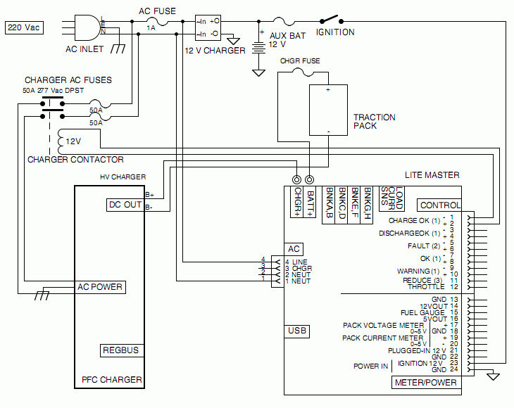
With this option, the BMS master controls the charger through a contactor to switch the charger's AC power on and off.

AC power switching
NOTE: pin-out of 4-wire AC connector is for rev C Master. For rev F Master use pins 3 and 4 instead.
A note about AC relays
You need a relay (or contactor) whose contacts are rated for BOTH the line voltage (i.e.: 125 Vac or 250 Vac), and for the current (i.e.: 15 A, or whatever the maximum input current of the charger is).
Just because a relay is rated for 30 A, it does not mean that it can switch the AC power.
AN AUTOMOTIVE, "CUBE" RELAY WILL NOT WORK!
With this option, the BMS master controls the charger through a relay that disables or enables the charger.
Controlling the charger's enable input requires a relay for isolation.
DO NOT CONNECT THE BMS MASTER DIRECTLY TO TO THE REGBUS CONNECTOR!
Because of its polarity, the RegBus input is not fail-safe, so you need to take precautions:
place the relay right at the reg-bus connector,
and do your best to make sure that there is no way that it becomes disconnected from the RegBus.
IF THE RELAY GETS DISCONNECTED, THE BMS WILL NOT BE ABLE TO PROTECT YOUR PACK!
While rev F BMS masters include an internal relay, that realy is normally open (closed = charge), which is the opposite of what the Manzanita Micro charger needs.
Therefore, you cannot use the internal relay to control the Manzanita Micro chargers.

Control input
NOTE: pin-out of 4-wire AC connector is for rev C Master. For rev F Master use pins 3 and 4 instead.
Control relay information
|
Relays can be "signal" or "power".
- "Power" relays can carry a lot of current, but must be used with at least 1 A, or their contacts will quickly oxidize
- "Signal" relays do not need to be operated at minimum current, but are not available with quick-connect tabs.
In this application we need a "signal" relay, because we ask it to switch a very low current.
|
|
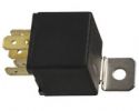
A typical automotive "cube" relay is nice because it is easy to mount and has quick-connect tabs.
However, it only comes in "power" type.
We know that, in all likelihood, you will use a "cube" relay, which is not ideal for this application.
So, we offer a workaround: add a capacitor (100 nF, 25V or more, any type) across the contacts of the relay;
when the relay contacts are open, the charger will place a voltage across the capacitor, charging it;
when the BMS master first energizes the relay, the contacts will close, quickly discharging the capacitor;
the resulting pulse of current will clean the contacts, ensuring long life for the relay.
If you do use a signal relay, the capacitor is not required, because the relay contacts remain clean even with no current.
|

Cube auto relay
|
REGBUS information
|
The charger is controlled through its RegBus connector.
It is intended for use with Manzanita Micro's MKII regulators.
It can be used to control the charger's operation.
By the way, "Bus" is spelled with only one 's', regardless of how it is spelled in the manual and on the front panel.
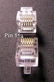
In many places the RJ25 connector is incorrectly called "RJ11".
If it has 6 contacts, they may call it RJ11 but it's really an RJ25.
The Modular RJ25 connector has 6 positions, 6 contacts.
Holding the connector in your hand tab side down with the cable opening toward you, the pins are numbered 1-6, left to right.
|

RJ25 connector
|
| Ckt #
| Color
| Old rev function
| Present rev function
|
| 1
| White or orange
| +5 volts output
- From 78L05 in charger
- Referenced to line voltage
|
| 2
| Black
| Hot reg input
- This line has a pull-down to ground inside the charger
- The hottest MKII regulator pulls up the voltage on this wire
- Pulling this line to the +5 V (pin 1) shuts down the charger
|
| 3
| Red
| Voltage control input
- On charge: external device may pull this line low to set regulator threshold up 10% (15.0 to 16.5 typical)
- On discharge: external device may pull this line low to indicated a battery has gone under the UV setpoint
| Low batt active low
|
| 4
| Green
| Common reference
- Referenced to line voltage: DO NOT connect to earth ground
|
| 5
| Yellow
| Cold reg input
- This line has a pull-up to +5V inside the charger
- The coldest MKII regulator pulls down the voltage on this wire
| EvilBus negative
- Digital communication for the Mark 3 Digital Regulators
|
| 6
| Blue
| Not used
| EvilBus positive
- Digital communication for the Mark 3 Digital Regulators
|
The colors above are standard. It seems that Manzanita Micro reverses the color order from the standards.
|
The charger must be adjusted as follows:
- DIP switch 1, 2 and 3 (closest to the edge of the box): OFF (Away from the "SWITCHES" label)
- This turns off the timer function
- (The timer function is useful to prevent thermal runaway in lead-acid batteries, and systems without a BMS)
- "VOLTS TRIM": set so that, when the pack is full and balanced, the charging current is reduced to 0
- Leave this adjustment up
- Allow the pack to be fully charged, and wait for it to become fully balanced
- Wait for the next time the charger starts charging again
- Start turning this adjustment down (counter-clockwise) until the current starts dropping
- Carefully adjust it a bit lower, until the current just goes down to 0
|
 
Manzanita Micro PFC charger settings
|
|
The BMS turns the charger off and on during balancing.
The problem with using the settings that Manzanita Micro insists on is that, if you do, once the BMS turns off the charger, it may not be able to turn it on again.
That is because of the Time-out function, and because of the Low-Voltage function:
- The Time-out function prevents the charger from coming back on if it has been turned off for some time (though DIP switch 8 should overcome this).
- The Low-Voltage function prevents the charger from coming back on if the battery voltage is still above a set, Low-Voltage point
Therefore, you need to turn Off DIP switch 1 to disable the Timer function, and allow the BMS to cycle the charger off and on.
|
- Start charging
- Check that there is charging current
- Disable charging
- Home / Test / Force outputs / HLIM / N
- Check that there is no charging current
- Re-enable charging
- Home / Test / Release outputs
- Check that there is charging current
Charger doesn't charge, even though BMS says that charging is OK
- Disconnect the RegBUS connector from the charger
- If charging starts:
- Check that there is no voltage on the input of the opto-isolator (with resistor) / relay / solid-state relay
- If there's voltage, check the HLIM polarity: Home / Set-up / Charge Limits / HLIM output polarity: should be "No"
- Check that there isn't short circuit on the output of the opto-isolator / relay / solid-state relay
- If charging doesn't start:
- Check the adjustments of the charger, especially the CURRENT adjustment and the voltage trimmer
- See if turning the charger's circuit breaker off and on fixes the problem
Charger doesn't turn off when BMS's HLIM line is tripped.
- Check that there is 12 V (or so) on the input of the opto-isolator (with resistor) / relay / solid-state relay
- Check the lines from the BMS controller to the opto-isolator / relay / solid-state relay
- If there's no voltage, check the HLIM polarity: Home / Set-up / Charge Limits / HLIM output polarity: should be "No"
- Check that there is a short circuit on the output of the opto-isolator / relay / solid-state relay
- Check the lines from the opto-isolator / relay / solid-state relay to the RegBUS connector


