Charger installation
Connecting the Lithiumate Lite master to the charger
You MUST provide a way for the BMS to shut down the charger, DIRECTLY!
Just because you have a BMS on board, don't think that your pack is protected.
Until you allow the BMS to shut down the charger, your pack IS NOT PROTECTED!
You MUST make sure that:
- When the BMS says "stop charging" the chargers does stop charging
- When the BMS says "restart charging" the chargers does restart charging.
- The BMS is powered whenever the vehicle is plugged in the wall (whether or not the charger is on at the time)
DO NOT SKIP THIS, or YOU WILL KILL YOUR BATTERY!
The BMS must be powered whenever the vehicle is plugged in the wall to protect the pack during charging, and to perform balancing even if the charger is off at the moment.
If there is any current in or out of the pack, yet the BMS is off, your pack IS NOT PROTECTED!
Near the end of charge, the BMS will turn the charger on and off, continuously, for a while.
You MUST allow the BMS to do that; otherwise, the BMS will not be able to balance the pack.
Just follow the instruction below, exactly, and you'll be fine.
These instructions assume a 1-phase charger that outputs at most 30 Adc.
|
You have four options. Pick one and implement it.
- Power the charger AC input through an AC relay, so that the BMS master can shut off power to the charger
- Wire the charger's control input to the BMS master, so that the BMS master can shut off power to the charger, through an external relay
- Same as above, but using an internal relay (Rev F Master only)
- Same as above, but connecting directly to the 12 V outputs of the Master
|
Connection location.
|
|
In this option, the BMS is able to turn the charger on and off by applying or removing AC power to the input of the charger.
It does so by driving a power relay between the AC power inlet and the charger's AC input.
|
|
User supplied required parts:
- 3-conductor cable that is UL or CSA or CE rated, and that is rated for the AC voltage and for the charger's input current
- AC power inlet
- Fuse rated for the AC voltage and for the charger's input current (2 fuses for 220 Vac split-phase operation)
- Fuse holder for the above fuse(s)
- Relay (or contactor) rated for the AC voltage and for the charger's input current, 12 V coil, DPST (2 Form A) (a SPST relay may be acceptable for 110 Vac operation)
- Suggested relay, but YOU are responsible for finding a part that will work in YOUR application
- Small gauge wire (such as 22 AWG)
Route the cable:
- From the vehicle's AC power inlet
- To a fuse holder
- To the AC relay (contactor)
- To the charger's AC power input
Connect the cable to the vehicle's AC power inlet:
- Green (or yellow-green) to the Earth terminal
- Black (or brown) to the Hot (or Line 1)
- White (or blue) to the Neutral (or Line 2)
Connect the cable to the fuse holder:
- Cut the black (or brown) wire in two and wire at either end of the fuse
- If 2 fuses, cut the white (or blue) wire in two and wire at either end of the other fuse
- (Note that the green ground wire continues uncut.)
Connect the cable to the relay (contactor) contacts:
- Cut the black (or brown) wire in two; wire the two ends to one set of NO contacts of the relay
- Cut the white (or blue) wire in two; wire the two ends to the other set of NO contacts (for SPST relays, leave the white wire uncut)
- (Note that the green ground wire continues uncut.)
Connect the cable to the charger's AC power input:
- Green (or yellow-green) to the Earth terminal
- Black (or brown) to the Hot (or Line 1)
- White (or blue) to the Neutral (or Line 2)
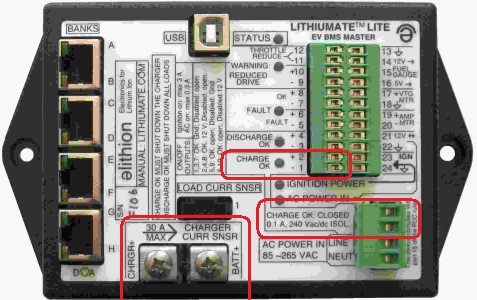
Connect the relay (contactor) coil to the BMS master:
- Use two small gauge wires to connect the relay coil to the two "Charge OK" terminals on the BMS master
A note about AC relays
You need a relay (or contactor) whose contacts are rated for BOTH the line voltage (i.e.: 125 Vac or 250 Vac), and for the current (i.e.: 15 A, or whatever the maximum input current of teh charger is).
Just because a relay is rated for 30 A, it does not mean that it can switch the AC power.
AN AUTOMOTIVE, "CUBE" RELAY WILL NOT WORK!
|
In this option, the BMS is able to turn the charger on and off by controlling the charger directly.
It does so by driving the charger's control input (usually through a small relay).
This option is easier, but is only available for chargers that have an enable input
|
|
User supplied required parts:
- 3-conductor cable that is UL or CSA or CE rated, and that is rated for the AC voltage and for the charger's input current
- AC power inlet
- Plug for the charger's AC power input
- Fuse rated for the AC voltage and for the charger's input current (2 fuses for 220 Vac split-phase operation)
- Fuse holder for the above fuse(s)
- Relay : 12 V coil, SPDT (1 Form C), ideally rated for signal operation / dry circuit
- Suggested relay, but not rated for signal, so you need to add a small capacitor (see below for more info) across the contacts
- Small gauge wire (such as 22 AWG)
Route the cable:
- From the vehicle's AC power inlet
- To the fuse holder
- To the charger's AC power input
Connect the cable to the vehicle's AC power inlet:
- Green (or yellow-green) to the Earth terminal
- Black (or brown) to the Hot (or Line 1)
- White (or blue) to the Neutral (or Line 2)
Connect the cable to the fuse holder:
- Cut the black (or brown) wire in two and wire at either end of the fuse
- If 2 fuses, cut the white (or blue) wire in two and wire at either end of the other fuse
- (Note that the green ground wire continues uncut.)
Connect the cable to the charger's AC power input:
- Green (or yellow-green) to the Earth terminal
- Black (or brown) to the Hot (or Line 1)
- White (or blue) to the Neutral (or Line 2)
Connect the relay coil to the BMS master:
- Use two small gauge wires to connect the relay coil to the two "Charge OK" terminals on the BMS master
Connect the relay contacts to the charger:
- Use two small gauge wires to connect the relay's NO and COM contacts to the two control terminals on the charger
A note about control relays
|
Relays can be "signal" or "power".
- "Power" relays can carry a lot of current, but must be used with at least 1 A, or their contacts will quickly oxidize
- "Signal" relays do not need to be operated at minimum current, but are not available with quick-connect tabs.
In this application we need a "signal" relay, because we ask it to switch a very low current.
|
|
A typical automotive "cube" relay is nice because it is easy to mount and has quick-connect tabs.
However, it only comes in "power" type.
We know that, in all likelihood, you will use a "cube" relay, which is not ideal for this application.
So, we offer a workaround: add a capacitor across the contacts of the relay (such as 100 nF = 0.1µF, ceramic disk or film, 25V or more);
when the relay contacts are open, the charger will place a voltage across the capacitor, charging it;
when the BMS master first energizes the relay, the contacts will close, quickly discharging the capacitor;
the resulting pulse of current will clean the contacts, ensuring long life for the relay.
If you do use a signal relay, the capacitor is not required, because the relay contacts remain clean even with no current.
|
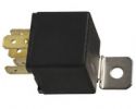
Cube auto relay
|
|
ONLY AVAILABLE IN A REV F BMS MASTER
WON'T WORK WITH A MANZANITA MICRO CHARGER
In this option, the BMS is able to turn the charger on and off by controlling the charger directly.
It does so by driving the charger's control input without the need for an external relay
This option is easier, but is only available for chargers that have an enable input that is open for disable, and closed for enable (not Manzanita), and rev F of the BMS master
|
|
User supplied required parts:
- 3-conductor cable that is UL or CSA or CE rated, and that is rated for the AC voltage and for the charger's input current
- AC power inlet
- Plug for the charger's AC power input
- Fuse rated for the AC voltage and for the charger's input current (2 fuses for 220 Vac split-phase operation)
- Fuse holder for the above fuse(s)
- Small gauge wire (such as 22 AWG)
Route the cable:
- From the vehicle's AC power inlet
- To the fuse holder
- To the charger's AC power input
Connect the cable to the vehicle's AC power inlet:
- Green (or yellow-green) to the Earth terminal
- Black (or brown) to the Hot (or Line 1)
- White (or blue) to the Neutral (or Line 2)
Connect the cable to the fuse holder:
- Cut the black (or brown) wire in two and wire at either end of the fuse
- If 2 fuses, cut the white (or blue) wire in two and wire at either end of the other fuse
- (Note that the green ground wire continues uncut.)
Connect the cable to the charger's AC power input:
- Green (or yellow-green) to the Earth terminal
- Black (or brown) to the Hot (or Line 1)
- White (or blue) to the Neutral (or Line 2)
Connect the charger's control input to the BMS master (not polarized):
- One wire to pin 1 of the 4-wire green AC power connector
- The other wire to pin 2 of the 4-wire green AC power connector
|
ONLY AVAILABLE WITH CHARGERS WITH A LOW VOLTAGE CONTROL INPUT
WON'T WORK WITH A MANZANITA MICRO CHARGER, ELCON CHARGER
In this option, the BMS is able to turn the charger on and off by controlling the charger directly from its 12 V outputs.
This option is easier, but is only available for chargers that have an enable input that is referenced to the 12 V supply, such as Brusa.
|
|
User supplied required parts:
- Black wire, rated for the DC voltage and for the charger's output current (recommended: 12 AWG stranded, 600 V, PTFE, -55° to +200° C)
- Red wire, (recommended: same specs as above)
- 2 each, ring terminals for wire above and for #10 stud (recommended: Tyco 2-36161-3)
- Charger
- Connector for charger's DC output
- Terminals to connect the wires to the battery terminals
- Fuses rated for DC, for the pack voltage and for the charger's output current (30 A maximum, else you may blow up the Lithiumate Lite's charger sensor input)
- Fuse holders for the above (in line or a fuse block)
Please note that 12 AWG (2 mm2) wire is sufficient to carry 30 Adc
(this type of wiring is "chassis wiring", which can handle more current).
Larger wire is wasteful, adds weight to the vehicle, and complicates wiring.
|
In a typical installation, the pack positive terminal goes to two places:
- From the charger: this line has a DC rated fuse, rated for the relatively small charging current, and goes through the battery current sensor built into the master
- To the motor driver: this line has a DC rated fuse, rated for the high load current, and goes through the load current sensor
Connect the charger's DC power output:
- Mount the fuse as close as practical to the traction pack.
- Red wire from the charger's '+' output, to the "Charger+" screw on the master (use a ring terminal)
- Red wire from the "Battery+" screw on the master (use a ring terminal) to the charger fuse fuse
- Red wire from that fuse to the battery '+' terminal
- Black wire from the charger's '-' output, to the battery '-' terminal
For additional protection in case of short to ground inside the traction pack, we recommend using an additional fuse, on the '-' wire between the pack and the charger.
|
Current sensing in a Lithiumate Lite master
|
Here are additional instructions for particular chargers: