Motor driver installation
Connect to the motor controller
You MUST provide a way for the BMS to shut down the motor driver, DIRECTLY!
Just because you have a BMS on board, don't think that your pack is protected.
Until you allow the BMS to shut down the motor driver (and any other load on the pack), your pack IS NOT PROTECTED!
These instructions assume that:
- The motor driver does not require the addition of a precharge circuit;
if it does, please follow the instructions of the motor driver manufacturer.
- If the motor driver has a CAN bus, it can operate without it (through wire control)
User supplied, required parts:
- Connectors for the motor driver
- Main fuse
- Throttle pot (5 kΩ)
Other user supplied parts:
You MUST provide a way for the BMS to shut down the motor driver, DIRECTLY!
|
You can do so in one of 4 ways:
- By shutting down the high voltage to the motor driver, or
- By shutting down the 12 V supply to to the motor driver, or
- By disabling the motor driver with a control line, or
- By killing the throttle voltage
DO NOT SKIP THIS STEP, OR YOU WILL KILL YOUR BATTERY!
Too many packs were lost during the FIRST test ride because this step was not yet implemented,
so DO NOT POSTPONE THIS STEP while you take your car for a spin for the first ride; resist the temptation!
Don't use the "dead EV on the train tracks" excuse: it's just a myth. The BMS will give the driver warning that the battery is nearly empty (unlike an ICE car, which will stop without warning if it runs out of gasoline).
|

Connection location.
|
As long as you follow these instruction carefully, you'll be fine.
Pick one of the 4 techniques below, AND IMPLEMENT IT.
|
In this approach to disabling the motor driver, the BMS controls the main contactor.
If the BMS needs to shut down the motor driver to protect the battery, it removes drive to the contactor coil.
- Wire the coil of the main contactor to the BMS master, to the "Discharge OK" terminals on the control connector (#3 and 4)
- If only the negative wire of the coil is available, connect it to the "Discharge OK -" terminal (#3)
- If only the positive wire of the coil is available, connect it to the "Discharge OK +" terminal (#4)
|

Motor driver disabling by removing the High Voltage
|
|
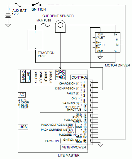
In this approach to disabling the motor driver, the BMS provides the 12 V power to the motor driver.
If the BMS needs to shut down the motor driver to protect the battery, it removes the 12 V to the motor driver.
- Run a wire between the motor driver and the BMS master
- Connect the wire to the 12 V supply input of the motor driver
- Connect the other end of the wire to the "Discharge OK +" terminal (#4)
Warning: the BMS master can only source 1 A.
If the motor driver requires more than that, then you need to add a small automotive relay between the BMS master and the motor driver.
|

Motor driver disabling by removing the 12 V
|
|
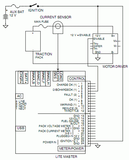
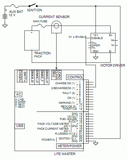
In this approach to disabling the motor driver, the BMS' "Discharge OK" output drives an enable line on the motor driver.
If the BMS needs to shut down the motor driver to protect the battery, it removes the 12 V to that control line.
- Run a wire between the motor driver and the BMS master
- Connect the wire to the enable input of the motor driver
- If the input is active high, connect the other end of the wire to the "Discharge OK +" terminal (#4)
|

Motor driver disabling through an enable line
|
- If the input is active low, connect the other end of the wire to the "Discharge OK -" terminal (#3)
|

Motor driver disabling through a disable control line
|
In this approach to disabling the motor driver, the BMS can kill the throttle voltage.
If the BMS needs to shut down the motor driver to protect the battery, it grounds the wiper output of the throttle, which is equivalent to releasing the throttle.
- Run a wire between the throttle pot (or the throttle connection at the motor driver) and the BMS master
- Connect the wire to the wiper of the throttle pot
- Connect the other end of the wire to the "Discharge OK -" terminal (#3)
Warning: if the motor driver supplies the throttle with a voltage is referred to the high voltage of the battery pack,
then use this method:
- Run two wires between the throttle pot (or the throttle connection at the motor driver) and the BMS master
- Connect the wires to the "Throttle reduce" terminals (#11 and 12)
Here are additional instructions for particular motor drivers:


