|
ElCon
Connecting a ElCon charger
You MUST provide a way for the BMS to shut down the charger, DIRECTLY!
Just because you have a BMS on board, don't think that your pack is protected. You MUST make sure that:
DO NOT SKIP THIS, or YOU WILL KILL YOUR BATTERY! The BMS must be powered whenever the vehicle is plugged in the wall to protect the pack during charging, and to perform balancing even if the charger is off at the moment. If there is any current in or out of the pack, yet the BMS is off, your pack IS NOT PROTECTED!
Near the end of charge, the BMS will turn the charger on and off, continuously, for a while. Just follow the instruction below, exactly, and you'll be fine. The ElCon charger hardware must be a current revision (its control connector must be made of black plastic with blue cover, and not a chrome DIN connector), and the charger must be programmed by ElCon with Algorithm 500-599 series (as indicated by a small, long white programming label near the serial number label marked such as "Alg 512 288V2K5W ...").
The ElCon charger is smart, and is great for packs used without a BMS that are already top balanced.
You MUST use a fuse ("Charger fuse"), between the pack and the Lithiumate Lite master's "Charger current sensor" input, as close as possible to the battery. The fuse must rated for DC operation, rated for the full pack voltage, and rated for the charger current (30 A maximum, else you may blow up the Lithiumate Lite's charger sensor input). This charger allows both control options: AC power and DC control With this option, the BMS master controls the charger through a contactor to switch the charger's AC power on and off. 
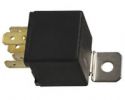
AC power switching A note about AC relays
You need a relay (or contactor) whose contacts are rated for BOTH the line voltage (i.e.: 125 Vac or 250 Vac), and for the current (i.e.: 15 A, or whatever the maximum input current of the charger is).
With this option, the BMS master controls the charger through an external relay that disables or enables the charger.
Controlling the charger's enable input requires a relay for isolation. 
Control input, external relay Control relay information
With this option, the BMS master controls the charger directly through an internal relay that disables or enables the charger.
ONLY AVAILABLE IN REV F BMS MASTERS The internal relay in the BMS master is not polarized: you can interchange pins 1 and 2. 
Control input, internal relay
|
By reading this page you acknowledge that you understand that this application note is just a suggestion, and that you will not hold Elithion responsible for its accuracy or appropriateness in you application, and that Elithion is not responsible for the fact that other manufacturers change their products in a way that may make these suggestions no longer applicable.