Warning installation
Provide a way to reduce drive when the battery is getting low
The idea here is that the best way to help the driver from getting stranded is to reduce the available drive
when any cell voltage starts getting too low.
That will help in the following ways:
- The resulting sluggishness warns the driver that the battery is low, so that the driver can take precautions
- Operating at low current reduces sag in the cell voltages, therefore allowing more charge to be extracted from them before the low voltage cutoff is reached
- Operating at low current makes the EV run in a more efficient range
You can implement this function in one of 2 ways:
- By suddenly putting the motor driver in a "Valet" or "Limp home" mode
- By gradually reducing the available drive
While this function is not required to protect the battery,
it is a great convenience to the driver, and we strongly recommend that you implement it.
When any cell voltage goes below a certain level, and while discharging, the BMS master will activate its "Low battery warning" output.
You can use that output to put motor driver in a "Valet" or "Limp home" mode.
It will also gradually reduce the resistance across the "Throttle Reduce" terminals, in proportion to how low that voltage gets.
You can use that resistance to gradually shunt to ground the voltage from the throttle pot's wiper.
These instructions assume that:
- The motor driver uses a 2 wire or 3 wire, 5 kΩ throttle pot (not HEPA throttle)
- The motor driver doesn't use part of the range in the throttle pedal for braking
|
Depending on the motor driver, you can implement this function in one of 2 ways:
- If the motor driver provides for a "Valet" or "Limp home" mode, by having the BMS engage it when it issues a low battery warning
- If the motor driver uses a throttle pot, by gradually shunting down the voltage from the throttle wiper to the motor driver
You can implement both valet mode and throttle reduction, but that is not usually necessary.
|
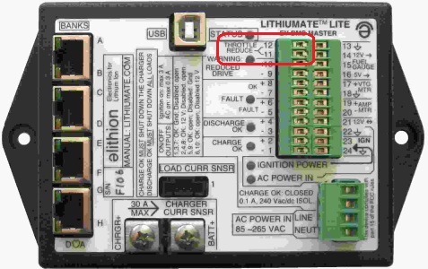
Connection location.
|
|
To implement the Valet mode:
- For a motor controller with an active high input, wire it to the "Low battery warning +" terminal of the control connector (# 10).
- For a motor controller with an active low input, wire it to the "Low battery warning -" terminal of the control connector (# 9).
|
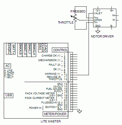
Valet mode
|
|
To implement Throttle reduction:
- Wire each of the "Throttle Reduce" terminals (# 11 and 12) to the two termimals of the throttle wiper
Note that the "Throttle Reduce" lines are isolated from the 12 V supply:
they can be used with motor drivers that drive the throttle pot with a supply that is not isolated from the battery pack.
Note that the "Throttle Reduce" lines are not polarized:
they can be interchanged without a problem.
|
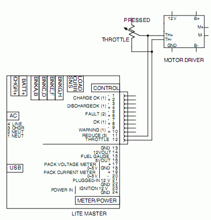
Throttle reduction with 2-wire throttle pot
|
|
To implement Throttle reduction:
- Wire one of the "Throttle Reduce" terminals (# 11 or 12) to the throttle wiper
- Wire the other "Throttle Reduce" terminal to the throttle negative terminal (the one connected to the wiper when the throttle is released)
Note that the motor driver must drive the throttle pot with a current limited output (such as by having a resistor in series with the output to the positive terminal of the pot).
Otherwise, if the driver is pressing the throttle all the way down, and at the same time the BMS is shunting the wiper voltage to ground,
that would short circuit the motor driver's supply, and may even damage the BMS master or the motor driver.
Note that the "Throttle Reduce" lines are isolated from the 12 V supply:
they can be used with motor drivers that drive the throttle pot with a supply that is not isolated from the battery pack.
Note that the "Throttle Reduce" lines are not polarized:
they can be interchanged without a problem.
|
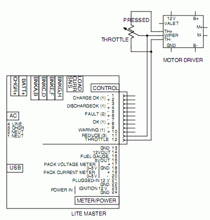
Throttle reduction with 3-wire throttle pot
|
|
Throttle reduction with a HEPA (Hall Effect) throttle by reducing the wiper signal is not recommended and in fact it may not be possible at all.
Motor driver manufacturers do not want you to mess with it, because doing so reduces the reliability advantage of HEPA over a standard throttle pot box.
Specifically, if the motor driver uses both signal wires from the HEPA, there is not easy way for a BMS to attenuate both lines at the same time.
This limitation is true of any BMS, not just the Lite.
The only correct way of reducing the drive when a HEPA is used, is for the motor driver to have a different input,
separate from the HEPA "Wiper" input, dedicated to torque reduction.
The Lithiumate Lite's "Throttle Reduce" function is designed to work only with a throttle pot, not with a HEPA throttle.
Therefore Elithion does not approve of any attempt to use the "Throttle Reduction" function with a HEPA throttle, and will not respond to any requests for tech support in these attempts.
Should you want to try to use the "Throttle Reduce" function with a HEPA throttle, you may want to start by placing a resistor (possibly 1 kΩ?) in series with the control line ("wiper") between the HEPA throttle and the motor driver.
Then, you may want to connect the two "Throttle Reduce" wires between the "Wiper" and "Ground" inputs of the motor driver.
But, again, Elithion does not approve of any such attempts and will not support them.
|
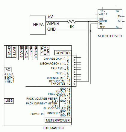
HEPA throttle reduction is not supported by the Lithiumate Lite
|
