Indicator installation
Wire to indicator lights on the dashboard
You may use lamps on the dashboard to indicate BMS status, and duplicate the functions of the LEDs on the BMS master:
- Warning
- Fault
- Discharge OK
- Charge OK
- Ignition power
- AC power
- Status
None of these indicators are required.
The Warning and Fault indicators are recommended.
The other ones are really not necessary from the point of view of a typical EV driver.
|
Use indicator lights that are rated 12 V, and no more than 0.5 A.
Except, the Status lamp must be 5 V.
LED indicators are OK, but, to work at 12 V, plain LEDs require a resistor in series.
LEDs are polarized, so connect the '+' of the LED to the '+' terminal on the BMS master, and '-' to '-'.
|
Connection location.
|
|
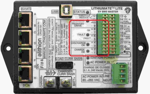
After installing the indicator lights on the dashboard and running wires to the BMS master, connect them as follows.
|
Dashboard indicators connected to a Lithiumate Lite BMS
|
Connect the 2 wires from the 12 V lamp to the "Lo-Batt Warning" terminals of the control connector (#9 and 10).
This should be an orange indicator.
Connect the 2 wires from the 12 V lamp to the "Fault" terminals of the control connector (#5 and 6).
This should be a red indicator.
Note that in hardware rev C the "OK" and "FAULT" legends on the front panel are swapped.
This is fixed in hardware rev E.
Connect the 2 wires from the 12 V lamp to the "Charge OK" terminals of the control connector (#3 and 4).
Connect the 2 wires from the 12 V lamp to the "Discharge OK" terminals of the control connector (#1 and 2).
You can connect the 2 from the 12 V lamp wires at any point in the vehicle where you find 12 V ignition and ground.
But, if you prefer to connect them to the BMS master, then connect them to the "Ignition" terminals
of the control connector (#23 and 24).
Connect the 2 wires from the 12 V lamp to the "AC 12 V" terminals of the control connector (#21 and 22).
Connect the 2 wires from the 5 V lamp to the "5 V" and "GND" terminals of the control connector (#? and ?).