Master installation
Mounting the BMS master, connecting it to the battery and to the rest of the EV
You MUST provide a way for the BMS to shut down
the charger, and the motor driver, DIRECTLY!
Otherwise,
1) the battery will not be protected, which is a FIRE danger,
2) the BMS will disable itself, requiring factory reactivation.
The BMS must be powered whenever there is any current in or out of the pack.
Otherwise the battery will not be protected.
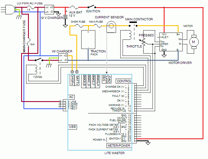
Basic EV schematic with a Lithiumate Lite BMS.
For simplicity, the connections to the cell boards are not shown.
NOTE: pin-out of 4-wire AC connector is for rev C Master. For rev F Master use pins 3 and 4 instead.
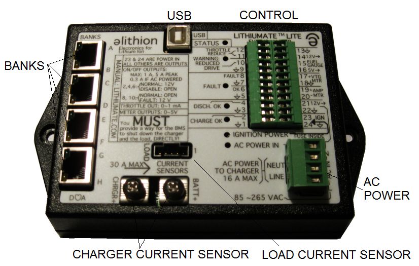
Connectors on Lithiumate Lite BMS master
|
Connect the AC power to the BMS master:
- Earth (green / yellow):
- Run a line from the Earth contact of the AC inlet to the chassis
- Neutral (blue or white):
- Run a line from the the Neutral contact of the AC inlet to the AC inputs of the BMS controller and the 12 V charger
- Hot (brown or black):
- Run a line from the the Hot (Line) contact of the AC inlet, to a 1 A fuse rated 250 Vac
- Run a line from the other end of the fuse to the AC inputs of the BMS controller and the 12 V charger
Connect the ignition power to the BMS master:
Note: for ignition power, use a 12 V auxiliary battery (don't use a DC-DC converter without a 12 V battery).
- +12 V (red):
- Find a +12 V line that is fused, and switched by the ignition switch
- Wire it to the BMS master, control connector, pin 23 ("IGN")
- ground (black):
- Find a ground line (a.k.a: "12 V common", or "12 V return", or" 12 V negative")
- Wire it to the BMS master, control connector, pin 24 ("GND" symbol)
|
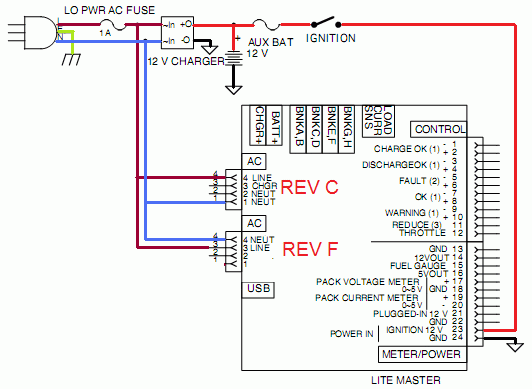
Lithiumate Lite master input power connections
NOTE: THE AC INPUT PINS DEPEND ON THE REV LEVEL OF THE MASTER:
REV C: pins 1 and 4.
REV F: pins 3 and 4.
|
|
Connect the AC power to the High Voltage charger AC input:
- Earth (green / yellow):
- Run a line from the Earth contact of the AC inlet and the chassis to the Earth connection of the High Voltage charger
- Neutral (blue or white):
- Run a line from the the Neutral contact of the AC inlet to the AC inputs of the High Voltage charger
- Hot (brown or black):
- Run a line from the the Hot (Line) contact of the AC inlet, to a fuse rated 250 Vac, 15 A or higher, as appropriate for the AC source
- Run a line from the other end of the fuse to a contact of a relay such as this one, rated for the load
- Run a line from the other contact of the relay to the AC input of the High Voltage charger
Connect the High Voltage charger DC output to the battery:
- B+ (orange or red):
- Wire the battery '+' terminal, through a DC rated fuse, to the "Battery+" screw on the master (use a ring terminal)
- Wire the charger's '+' output, to the "Charger+" screw on the master (use a ring terminal)
- B- (orange or black):
- Wire the battery '-' terminal to the the charger's '-' output
Connect the charger relay coil:
- Wire the coil terminals of the charger relay to the "Charge OK" terminals of the master (pins 1 and 2)
|
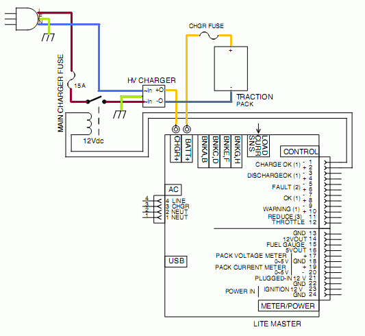
Lithiumate Lite master charger connections
|
|
Connect the battery to the motor driver:
- B+ (orange or red):
- Wire the battery '+' terminal to the DC-rated, Main Fuse
- From the other end of the Main Fuse, wire through the load current sensor; the arrow on the sensor must point away from the battery
- From there, wire to the '+' contact of the Main Contactor
- Wire the '-' contact of the Main Contactor to the "B+" input of the Motor Driver
- B- (orange or black):
- Wire the battery '-' terminal to the "B-" input of the Motor Driver
Connect the Main Contactor coil:
- Wire the coil terminals of the Main Contactor to the "Discharge OK" terminals of the master (pins 3 and 4)
Connect the throttle reduce:
- Wire the "Wiper" and "-" terminals of the throttle pot to the "Throttle Reduce" terminals of the master (pins 11 and 12)
Connect the load current sensor:
- Plug in the load current sensor (black connector) into the master
|
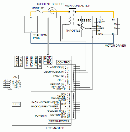
Lithiumate Lite master motor driver connections
|