Install cell boards
Install cell boards onto the cells and wire them
Li-Ion CELLS CAN CAUSE SERIOUS DAMAGE IF SHORT CIRCUITED!
DANGEROUS VOLTAGES: SHOCK DANGER!
A cell board WILL be damaged if you do any of these common mistakes.
A DAMAGED CELL BOARD MAY DRAIN ITS CELL!
Before working on cell boards, disconnect the battery from EVERYTHING else!
Divide the battery into banks of contiguous cells (mechanically and electrically contiguous).
Each bank of N cells will:
- Need N-2 mid cell boards
- Need a negative end cell board
- Need a positive end cell board
- Use 1/2 of a breakout
- Use 1/2 of an RJ 45 cable
For each bank:
- Prepare a Cell Board for each cell in series in that bank
- Prepare 1 Positive End Cell Board for the most positive cell in the bank
- Prepare 1 Negative End Cell Board for the most negative cell in the bank
- Prepare mid-bank end Cell Boards for the the rest of the cell in the bank
- Orient the Cell Board properly DO NOT CONNECT BACKWARDS!
- The ring terminal that is mounted directly to the Cell Board (labeled 'B-' on the PCB) goes to the negative terminal
- The ring terminal that is mounted on a red wire (labeled 'B+' on the PCB) goes to the positive terminal
- The electronic components go towards the cell, the LED towards you
- Place a Cell Board on the negative terminal of its cell
- Remove the bolt from the cell's negative terminal, keeping the power connection in place
- Place the 'B-' ring terminal (mounted directly to the Cell Board) on top of the power connection on the negative terminal
- Put the bolt back in and secure it
- Connect the Cell Board to the positive terminal
- Touch that terminal with the 'B+' ring terminal (mounted on the red wire)
- The LED will blink twice, repeated a total of 3 times
- If the LED doesn't blink when first connected, the board is damaged: discard it
- Remove the bolt from a cell's positive terminal, keeping the power connection in place
- Place the 'B+' ring terminal (mounted on the red wire) on top of the power connection on the positive terminal
- Put the bolt back in and secure it
- Repeat with the other cells in the bank
For each pair of adjacent cell boards:
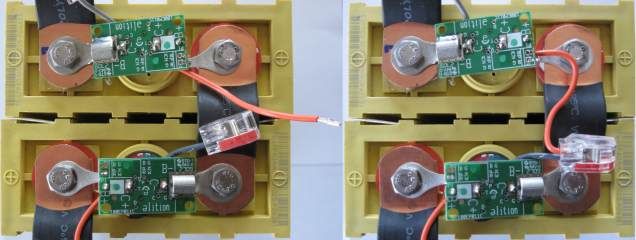
- Point the gray wire towards the negative terminal of the cell
- Route the orange wire along the power bus bar between cells, and then to the gray wire in the adjacent Cell Board
- If the orange wire is too long, cut it shorter, so that it ends at the splice on the gray wire
- Strip the end of the orange wire 0.4" (1 cm)
- Insert the orange wire in an open slot in the splice at the end of the gray wire, push all the way in
- If required, secure the orange wire in place (use wire ties; do not twist it around the red wire or the bus bar)
|
Cut and strip orange wire (left)
and insert in splice (right).
|
For each pair of physically adjacent banks:
- Install a bank breakout close to those banks.
- Route the green cables to one bank and the yellow wires to the other bank.
- For each bank, connect the connector with the wide release tab to the negative end cell board, and the connector with the narrow release tab to the positive end cell board.
- Use a shielded modular RJ45 connector to connect the breakout to the BMS master.